Resonance - The Hidden Threat
You have balanced your machine properly (at least twice), you have aligned it, you have checked the mountings and it still vibrates like an old washing machine for no apparent reason... The reason is probably resonance.
MECHANICAL RESONANCE is the tendency of a mechanical system to respond with greater amplitude when it is vibrated at a frequency corresponding to its natural frequency than when vibrated at other frequencies. Every mechanical object has natural frequencies at which it vibrates more easily and more strongly than at other frequencies.
You can see this in everyday life. For example, there may be something in your car that does not vibrate very much, but if you make a small change to the engine RPM, you will hear much stronger vibrations. This is an example of when the speed of the engine is close to the natural frequency of the thing that is vibrating. It is very dangerous to operate machines close to their natural frequencies because even a small unbalance can generate extremely high vibrations. This can easily destroy the machine. We usually encounter the resonance problem at the machine foundation. When the machine speed is close to the natural frequency, we measure high vibrations for no obvious reason. The maintenance team usually carries out all the standard procedures such as balancing, alignment and bearing mounting checks, but the vibrations still remain high.
The resonance problem is the cause.
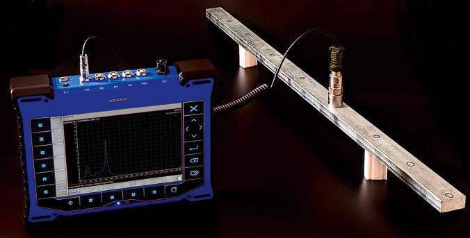
Now I would like to tell you how to use the bump test measurement. It is the perfect measurement for situations where you suspect a resonance problem. We have used a steel beam for this simple demonstration. Imagine it is a machine foundation. We used a standard 100 mV/g accelerometer and a hammer. The Adash VA4Pro and VA5Pro vibration analysers include a super easy-to-use bump test mode. No settings are required. Just place the sensor on the object to be measured and hit it with a hammer. Let's look at the final graph. [1] The high peaks on the spectrum are the natural frequencies, in our case 100 Hz and 280 Hz. There will be a resonance problem if the machine speed is close to these two frequencies. We can shift the natural frequency to solve the problem by reinforcing the structure to change the natural frequency. For example, we could add another support in the middle and the natural frequencies will decrease. [2] In the real world, a fixed pillar would be welded to the machine foundation and the natural frequencies would not only be reduced, but also re-tuned. Every mechanical object has its mode shapes.
For simple objects you can calculate the mode shapes, but for a complicated construction it is not possible, you have to measure it. We analysed the frame by hitting it with a hammer. When the machine is running, you can also measure the vibration levels at each point. In this case, the frame is not excited by the hammer, but by the operational speed. The vibration levels will not be the same at all points on the machine. If you measure them all and draw the arrows again, you will get the first operational deflection shape of the machine. To find the next operational deflection shapes, you need to know the spectrum of vibration at each point. Knowing the machine shapes is important for understanding the machine.
The ADASH vibration analyzers include the ADS (Animated Deflection Shapes, or Operating deflection shapes) mode. It allows you to measure these shapes very easily and then animate the results to illustrate. In the next example I will show you why it is important to know the mode shapes that are causing the vibration problem. We have used the shaker and the rubber cord. The first natural frequency is 10 Hz and you can see the first mode shape (Figure 3). If I need to reduce the vibration level, I can add the support in many places and it will work. But sometimes the second mode shape might be the problem rather than the first. Now you can see the second natural frequency (Figure 4). The position of the pillar is now much more important. If I put it in the middle, the vibration remains unchanged. Back to our first example with the steel beam. The initial overall vibration was 6.34 g. We added a pillar in the middle and the main natural frequency at 100 Hz decreased about 4 times. However, the second natural frequency at 280 Hz has only decreased about 2 times and is now affecting our frame almost as much as the first frequency. The overall vibration is now 3.19 g. We then moved the pillar from the middle to 1/3 of the way between the end pillars. The new natural frequencies are as follows. [3] You can see that the first frequency has remained the same, but the second has been reduced more. The overall vibration was reduced to 2.56 g.
THE BUMP TEST IS THE PERFECT MEASUREMENT FOR SITUATIONS WHERE YOU SUSPECT A RESONANCE PROBLEM.
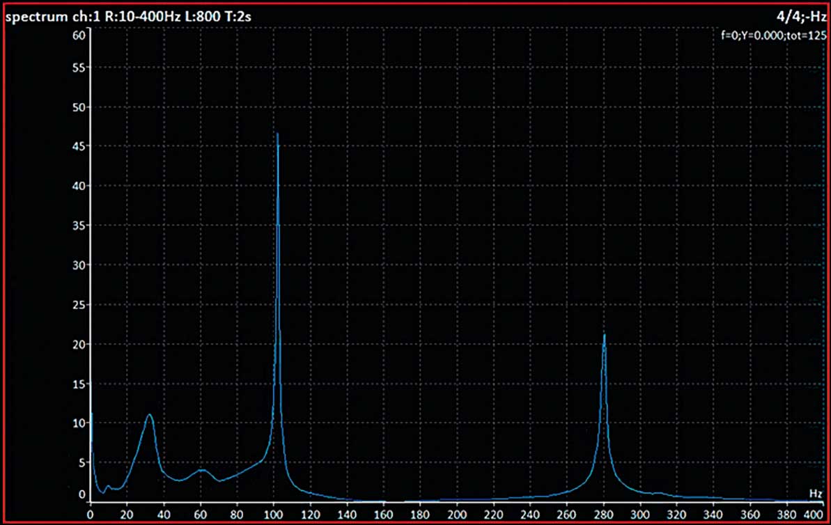
Graph 1: Initial spectrum
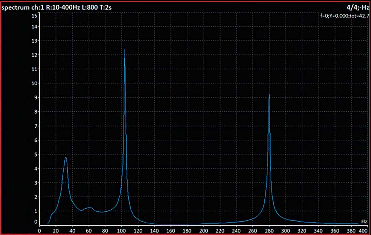
Graph 2: Changed spectrum
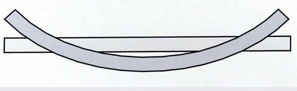
Figure 1: Every mechanical object has its mode shapes.
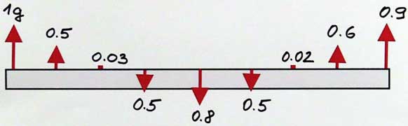
Figure 2: The length of each arrow is proportional to the g value at that point.
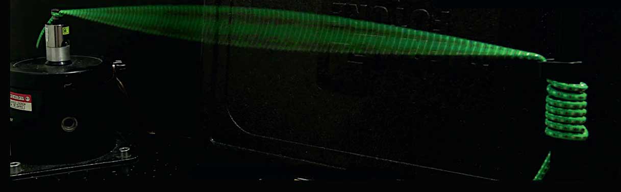
Figure 3: The first natural frequency is 10 Hz.

Figure 4: Second natural frequency.
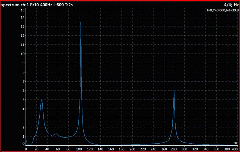
Graph 3: Final spectrum