Most Common Myths about Accelerometers and Frequency Range
In this article I will talk about the frequency range of accelerometers and about common mistakes in understanding them.
The most common accelerometer has a sensitivity of 100 mV/g. The frequency range declared by its manufacturer is: 0.5 Hz - 15 kHz, with a bias of plus or minus 3 dB. It might seem that +/- 3 dB is not too much, that it is something like +/- 3 percent. But this is not true. The +/- 3 dB is much, much more. Minus 3 dB is minus 30 percent, plus 3 dB is plus 40 percent. But the frequency range is not the main issue here.
Let's suppose that the response function is flat. Most users would like to have a very low frequency limit. They say: "I need to measure a low speed machine, my machine speed is only 30 rpm, I need to measure 0.5 Hz". But that is not a relevant reason. Let me give you an example: If I want to measure the acceleration on a low frequency, what acceleration can I expect? Would it be 1g, for example? Most people cannot imagine vibration acceleration and vibration velocity. Everyone can imagine the displacement. If you say that a machine is vibrating +/- 3mm, then everyone understands. So we can use this formula to convert acceleration to displacement and displacement to acceleration: acc [m/s2] = disp [m] * (2 × π × speed [Hz])2 Using this simple math, we can convert 1g to metres. If the speed is 30 rpm, this means 0.5 Hz. (Remember to convert g to m/s2 first.) The corresponding displacement is 1 m. Not one millimetre, but one meter. No machine could work at that level of vibration. The corresponding velocity level is 3 200 mm/s, it is 125 ips, impossible... Now let us suppose that the displacement level is 1 mm. The corresponding acceleration level is 0.01 m/s2. It is 0.001 g. If the sensitivity of the sensor is 100 mV/g, then the voltage for 0.001 g is 0.1 mV. It is not too much. Can you measure such a voltage level? The answer is NO, because the usual sensor noise level in the field is 0.2 to 0.4 mV. With such noise it is very difficult to measure the 0.1 mV because it is below the noise level. But let's go back to the basic question. Why measure the amplitude at 0.5 Hz? Another answer is: "I would need it if I wanted to balance the machine or check for looseness or misalignment". Yes, in these cases I need to measure the level at the speed frequency, however it is not necessary. If the speed is so low, then you should have an unbalanced mass of tens of kilograms to increase the vibration level. The centrifugal force depends on the square of the speed. At 30 rpm it will be very low. Another reason could be to measure the condition of the roller bearing.
And this is the key point
For this measurement I do not need the low frequency. When the bearing balls pass through scratches, or if you like, bearing pitting, on the inner and outer rings, then the shocks appear in the time signal. The natural frequencies of shocks are very high. Typically between 500 Hz and 25 kHz. We do not need to measure low frequencies, we need to measure these very high frequencies. And this is not easy for low speed bearings (machines). We need a high resolution of the signal (high sampling frequency) and at the same time we need a long time signal because the time interval between shocks is very long. So, the whole measurement is extremely demanding on data processing and data storage. ADASH has therefore developed and implemented the ACMT measurement method for low-speed bearing analysis, which uses smart compression to overcome these problems and keep most of the information in the vibration signal. The next most common misunderstanding are bearing fault frequencies. They can be very low for low speed machines and again users are applying the wrong rule. They may think that the accelerometer must be able to measure this frequencies. But this is wrong. The fault frequency is the repeating frequency of the shocks, it is not a pure sine frequency that should be captured by a vibration sensor. We need to measure the natural frequencies of the shocks. And they are again higher than 500 Hz.
THE NATURAL FREQUENCIES OF SHOCKS ARE VERY HIGH. TYPICALLY BETWEEN 500 HZ AND 25 KHZ.
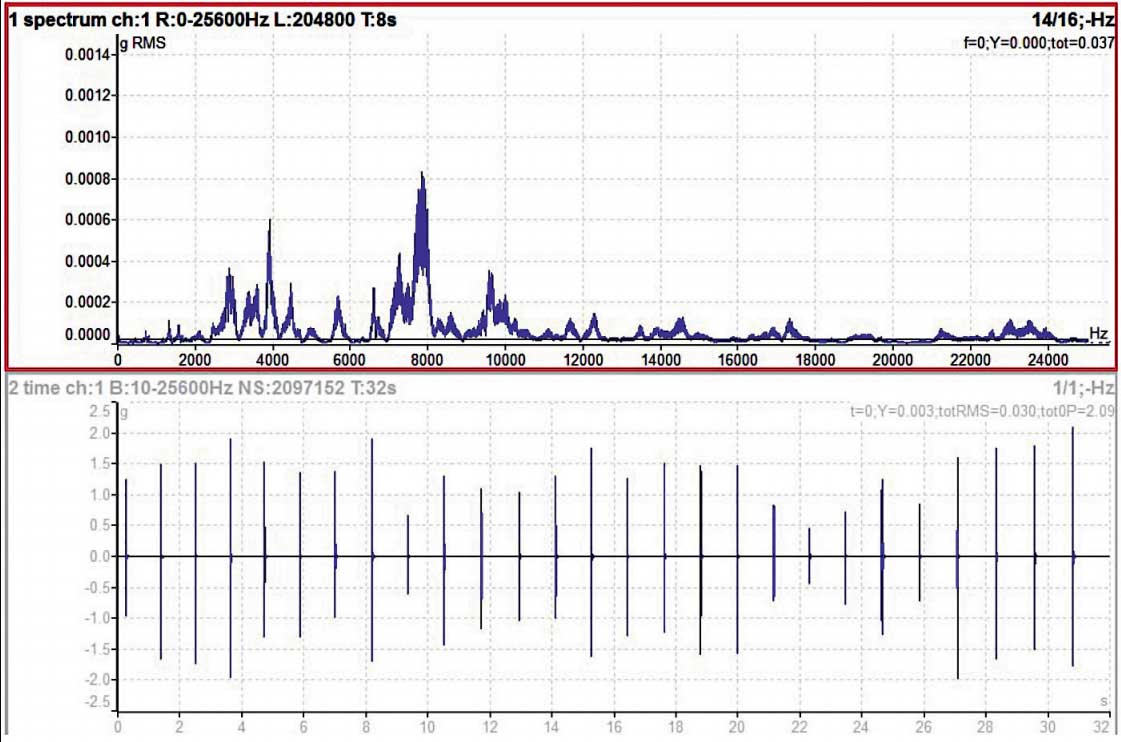
Figure 1
Figure 1 shows the vibration spectrum and time signal (measured on a low speed bearing). The range is 25 kHz. All the higher amplitude lines are in the range of 2 kHz and above. Please notice those very low g amplitudes in spectrum. The spectrum shows the energy of the signal. In this vibration signal we only see shocks without significant energy. This is why the spectrum shows very low values.
THE BEARING FAULT FREQUENCY IS THE REPEATING FREQUENCY OF SHOCKS.
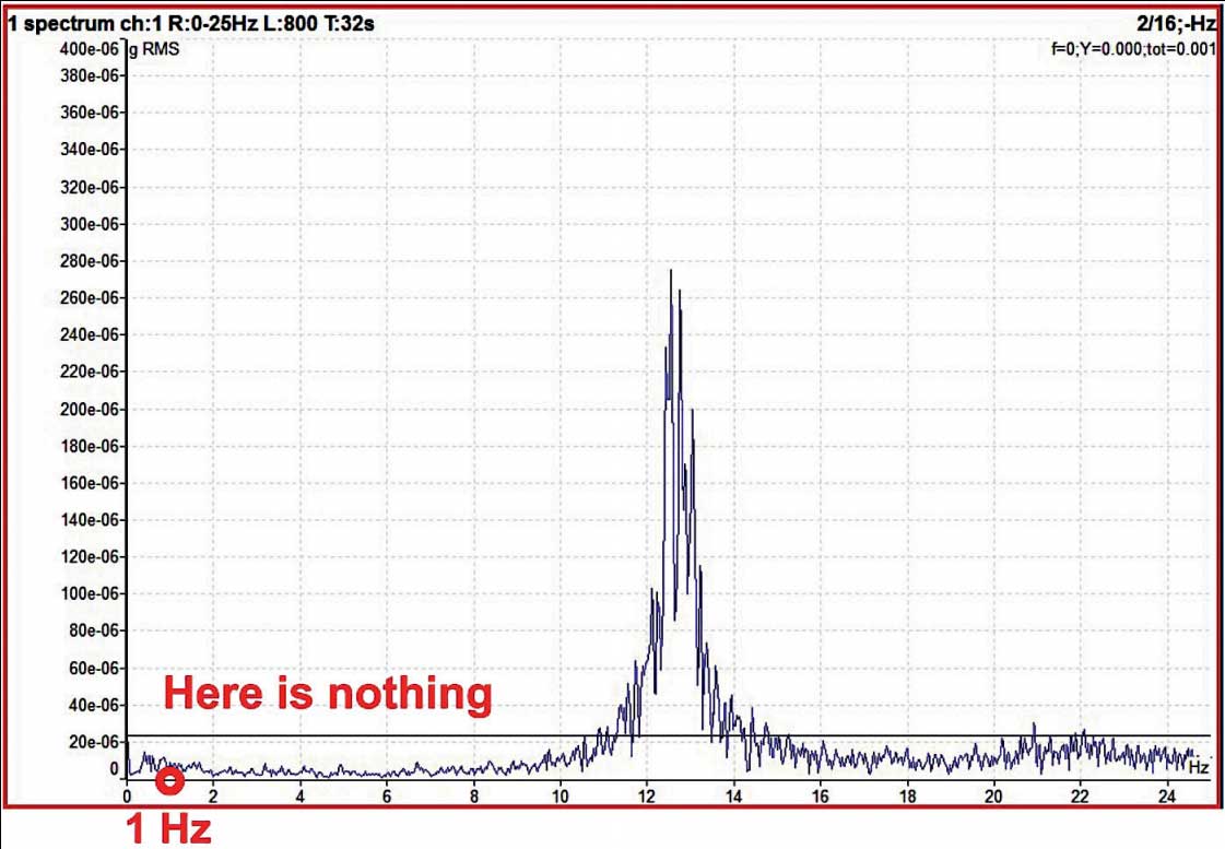
Figure 2
In Figure 2 we have measured the vibration spectrum only in the 25 Hz range. The repeating frequency of the shocks for this bearing is around 1 Hz. You see nothing around 1 Hz. If we want to see the repeating frequencies in the spectrum, we have to apply demodulation. That means we have to add the energy. The demodulated vibration spectrum can display something visible. The demodulated spectrum uses the time signal that is enveloped. We only want to measure in the 500 Hz to 25 kHz band. We are not interested in the lower frequencies. You can think of enveloping as a simple electrical circuit: the impulse comes and charges the capacitor, and then the capacitor is discharged by the resistor. The discharge is much longer than the length of the original shock. This is the extra energy that helps us in the spectrum. And it really helped. In the third picture you can see the 0.85 Hz repeating frequency and its harmonics. The harmonics always occur because the enveloped signal is distorted. It is not a pure sine wave, which can only show one line in the spectrum.
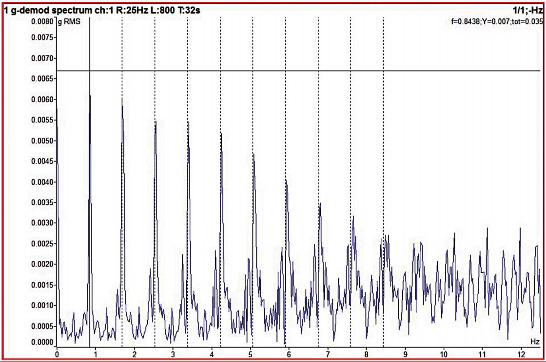
Figure 3